|
Some basic wireless concepts:
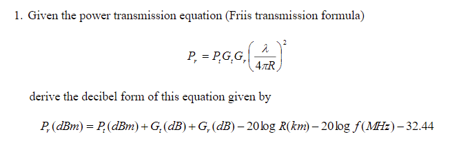
Free space path loss formula: Forexample, at L-band, let's say 1 GHz, we have Assuming antenna gains of 0 dB, at 10km we have. Loss = -112.44 dB This means our transmitted signal should be 112.44 dBm to receive 0dBm signal. so we can conclude two times distance ~ 6 dB loss Two times Frequency ~ 0.5 Range Two times frequency ~ 6 dB loss
Phase noise: Phase noise is the noise spectrum that is seen spreading out either side of a signal as a result of the phase jitter that exists. Noise arising from the short term phase fluctuations that occur in a signal. The fluctuations manifest themselves as sidebands which appear as a noise spectrum spreading out either side of the signal.B Phase noise is of particular importance to RF designer. Express in dBc/Hz. which means: dB down in level from the carrier proportional to the bandwidth. e.g. when we say phase noise is -100dBc/Hz @ 100 Hz : This means when frequency offset is 100 Hz, the phase noise is -100dBc/Hz
|
||||||||||||||||||||||||||||||||||||||||||||||||||||||||||||||||||||||||||||||


 Forexample many commercial GPS receiver sensitivity is around -167 dBm.


| GLONASS | GPS | ||
|---|---|---|---|
| Constellation | Number of satellite | 24 | 32 |
| Number of orbits | 3 | 6 | |
| Orbital inclination | 64.8° | 55° | |
| Orbital radius | 25,510 km | 26,560 km | |
| Orbital altitude | 19,130 km | 20,200 km | |
| Orbit period | 11 h 15.8 min | 11 h 58 min | |
| Signal characteristics | Multiplexing | FDMA | CDMA |
| Carrier frequencies | 1602 + k × 0.5625 MHz 1246 + k × 0.4375 MHz |
1575.42 MHz 1227.60 MHz |
|
| Code frequencies | C/A code: 0.511 P code: 5.11 |
C/A code: 1.023 P code: 10.23 |
|
| Broadcast ephemerides | Position, velocity, acceleration | Keplerian elements | |
| Coordinates system | PZ-90.02 | WGS-84 | |
| Time system | GLONASS time | GPS time | |
Smith Chart:
Using this chart you can find the impedance of a transmission line and antenna system as a function of frequency. These days people use ADS software.
RTL (Register Transfer Level) vs SLD (Sequential Logic Design):
In RTL Design the basic building blocks are registers, Multiplexers, Adders. In Sequential Logic Design the basic building blocks are the Logic Gates, Flip-Flops. RTL is more data flow approach but SLD is more hardware in nature.
Direct Conversion Receiver:

Coherent Time:
Electromagnetic: the time over which a propagating wave may be considered coherent, meaning that its phase is, on average, predictable.
Communication: the time duration over which the channel impulse response is considered to be not varying (e.g. Doppler)
More explanation: the time domain dual of Doppler spread and is used to characterize the time varying nature of the frequency dispersiveness of the channel in the time domain. The Maximum Doppler spread and coherence time are inversely proportional to one another. T_c = 1/f_m
where f_m is the maximum Doppler spread or maximum Doppler shift
Coherent Bandwith:
A bandwidth (range of freq) which channel can be considered flat. Similarly to coherent time, it has inversely proportional to delay spread.
B_c = 1/D. where D is the delay spread in second.
if the coherent bandwidth (B_c) > Signal Bandwidth ==> channel is flat.
Rake Receiver:
Rake receiver, which exploits multipath delay components to improve the performance of the system. A rake receiver combines the information from several correlators, each one tuned to a different path delay, producing a stronger version of the signal than a simple receiver with a single correlation tuned to the path delay of the strongest signal.
In other words,
a radio receiver designed to counter the effects of multipath fading. It does this by using several "sub-receivers" called fingers, that is, several correlators each assigned to a different multipath component. Each finger independently decodes a single multipath component; at a later stage the contribution of all fingers are combined in order to make the most use of the different transmission characteristics of each transmission path. This could very well result in higher signal-to-noise ratio (or Eb/N0) in a multipath environment than in a "clean" environment.
The idea to boost the strong signal components and attenuate the weak (relatively noisy) components, as performed in MRC diversity, is exactly the same as the type of filtering and signal weighting used in the matched filter receiver. A particularly interesting application of this concept is the Rake receiver for detecting direct-sequence CDMA signals over a dispersive channel.The rake receiver consists of multiple correlators, in which the receive signal is multiplied by time-shifted versions of a locally generated code sequence. The intention is to separate signals such that each finger only sees signals coming in over a single (resolvable) path. The spreading code is chosen to have a very small autocorrelation value for any nonzero time offset. This avoids crosstalk between fingers.In practice, the situation is less ideal. It is not the full periodic autocorrelation that determines the crosstalk between signals in different fingers, but rather two partial correlations, with contributions from two consecutive bits or symbols. It has been attempted to find sequences that have satisfactory partial correlation values, but the crosstalk due to partial (non-periodic) correlations remains substantially more difficult to reduce than the effects of periodic correlations. The rake receiver is designed to optimally detected a DS-CDMA signal transmitted over a dispersive multipath channel. It is an extension of the concept of the matched filter.
Central Limit Theorem:
The central limit theorem states that if you have a population with mean μ and standard deviation σ and take sufficiently large random samples from the population with replacement text annotation indicator, then the distribution of the sample means will be approximately normally distributed. This will hold true regardless of whether the source population is normal or skewed,
Shanon Theorem:
Tightest upper bound on the information rate of data (C) that can be communicated at an arbitrarily low error rate using an average received signal power through an analog communication channel subject to additive white Gaussian noise (AWGN) of power:
C = bandwidth X log2(1 + SNR)
Impossible to transmit data at faster rate os C without error.
C= capacity (bits/s)
SNR in Watt /Watt
with MIMO steams ==> C = M X BW X log2(1+SNR)
M ==> MIMO steams
Example: We have a wireless system with RF Bandwidth of 20 MHz in SNR of 10dB. What is the maximum data rate we can get?
10dB == 10^(10/10) =10 therefore, C=20e6log2(11)=~69 Mbps

Stationary Process wide sense stationary(WSS):
A random process that parameters such as mean and variance do not change over time. e.g. white noise.
The wide sense stationary uncorrelated scattering (WSSUS) model is commonly used for multipath fading channels. WSSUS channel assumes that the channel correlation function is invariant over time, and that the scatterers with different path delays are uncorrelated. The WSSUS assumption is realistic to describe the short-term variations of the radio channel.
Wiener–Khintchine theorem:
States that the autocorrelation function of a wide-sense-stationary random process has a spectral decomposition given by the power spectrum of that process or simply
PSD is equal to the Fourier transform of the autocorrelation function(treated as a function of the delay).
why this theorem important? in LTI system. The Fourier transform of the autocorrelation function of the output of an LTI system is equal to the product of the Fourier transform of the autocorrelation function of the input of the system times the squared magnitude of the Fourier transform of the system impulse response
GFSK VS FSK:
Converts the digital baseband signals (0 or 1) to passband frequency modulated signals.
FSK modulated signals have better noise immunity in comparison with the amplitude modulated signals, and FSK modulated systems are less complicated for demodulation.
Gaussian (GFSK) modulation is the Gaussian filter applied FSK modulation. GFSK uses a
Gaussian filter to smooth the beginning of each digital symbol before the frequency modulation
procedure.

Antenna Diversity:
2 types: SIMO and MIMO (single/multiple inputs multiple outputs)
Why?
Because: *Diversity Gain *Fading mitigation *Security
maximum-ratio combining (MRC):
The idea is to boost the strong signal components and attenuate the weak (relatively noisy) components, as performed in MRC diversity,
e.g. in BPSK, Expressing in decibels, with two receive antennas, we GAIN 3dB.
for N RX antenna: BER=0.5*erfc(sqrt(N*Eb/N0))
Lease square in maximum-ratio-combining (MRC):

which means that the signal from each antenna is rotated and weighted according to the phase and strength of the channel, such that the signals from all antennas are combined to yield the maximum ratio between signal and noise terms.
Analog to Digital Converter (ADC):

From Channel Impulse Response to Delay/Doppler Power Spectrum :

CDMA:

IQ Imbalance :
IQ imbalance is a performance-limiting issue in the design of direct conversion receivers, also known as zero intermediate frequency (IF) or homodyne receivers. Such a design translates the received radio frequency (RF, or pass-band) signal directly from the carrier frequency (fc) to baseband using only one mixing stage. The traditional heterodyne receiver structure needs an IF stage between the RF and baseband signals. The direct conversion receiver structure does not have an IF stage and does not need an image rejection filter. Due to the lower component count, it is easier to integrate. However, a direct-conversion RF front-end suffers from two major drawbacks: one is IQ imbalance and the other is DC offset. When designing a homodyne receiver, control of IQ imbalance is necessary to limit signal demodulation error.
IQ imbalances occur due to mismatches between the parallel sections of the receiver chain dealing with the IQ signal paths. The local oscillator (LO) generates a sine wave and a copy of that sine wave that is delayed by 90 DEGREES. When the direct LO output is mixed with the original signal, this produces the I signal, whereas when the delayed LO output is mixed with the original signal, that produces the Q signal. In the analog domain, the delay is never exactly 90 degrees. Similarly, the analogue gain is never perfectly matched for each of the signal paths.
Minimum Mean Square Error (MMSE)
An estimation method in signal processing
We have prior information about the range of a parameter (Bayesian situation)(e.g. noise)
We can make better posterior estimates as more observations become available.
Assume n is a random variable (e.g. noise) and X is input data to the system.
n has a probability density function of p(n)
X and n have joint pdf of p(n,X)
MMSE estimation of n = n^ = g(X) that minimizes E[(n-n^)^2)]
n^ = E[n|X] = integral(n*p(n|X)dn)
Flicker noise or pink noise or 1/f noise:
Definitions:
*the noise power is inversely proportional to the frequency
*often occurs as a resistance fluctuation
*Passive components have 1/f noise and current noise
*low resistances the 1/f noise and current noise are usually too small to be considered


How to remove flicker noise?
Answer: Chopper stabilization works by alternating or chopping the input signals at the input stage and then chopping the signals again at the output stage. This is the equivalent to modulation using a square wave. Chopper stabilization, or chopping, is a technique to reduce amplifier offset voltage.
first the low-frequency signal is shifted to high frequency by multiplying it with high-frequency carrier, and it is given to the device affected by the flicker noise. The output of the device is again multiplied with the same carrier, so the previous information signal comes back to baseband, and flicker noise will be shifted to higher frequency, which can easily be filtered out.
Z Transform and Z plane Filter Design


Difference between FIR (Finite Implulse Response) and IIR (Infinite Impulse Response) filters?:
| FIR | IIR |
Linear Phase Response |
Nonlinear Phase Response |
Group delay is better |
Gourp delay is not good |
| More memory | Less Memory |
| Only depends on Input | Depends on both input and output |
| Only zeros | both zeros and poles (numerator and denumerator) |
| Easy to implement | Difficunt to implement |
| Tapping high order | Tapping lower order |
FIR filter:


1) Open Matlab "filterdesigner" --> Get coefficients --> change filter structure to get nominator and denominator for IIR
2) Load FIR and IIR MATLAB Simulink models
DOWNLOAD SIMULINK FILE:http://nhz.us/file.php/1/files/My_FIR_IIR.slx3) Replace coefficients
IIR Filter:


Simulink result:
Simulink result:
Red --> IIR Blue --> FIR

MLSE (Maximum Likelihood Sequence Estimation) in simple words
Estimate the most likely sequence of transmitted symbols in a communication system.
In communication systems, the transmitted signals may get distorted due to various factors such as noise, interference, and multipath propagation. MLSE helps to estimate the original transmitted sequence by finding the sequence that is most likely to have produced the received signal, given the knowledge of the channel and the statistical properties of the transmitted symbols.
Two general steps:
1) received signal is compared to all possible transmitted symbols (Sequence Estimation) --> sensitivity vs complexity -->better if there is a relationship between received signal and different symbol periods e.g. convolutional coding, continues phase modulation
2) calculate the likelihood of each possible sequence of transmitted symbols (Maximum Likelihood) --> value of squared Euclidean distances between hypothetic signals and the received signal --> sometimes simplified to cross correlation
Find Markov model --> state of signal --> intersymbol relationship or correlation e.g. MSK phase changes by 1/2*pi at each sample time

or in case of QPSK

which in QPSK there is no dependency from symbol to symbol so no benefit to decode a sequence
Adaptive Frequency Hopping (AFH) in Bluetooth LE:
The central device initiates channel assessment, scan each channel's quality using metrics like energy levels (e.g., RSSI) against a predefined threshold or incorporating historical Packet Error Rate (PER). Simultaneously, if the feature is supported and enabled by the central, the peripheral device also monitors channel quality based on its reception, tracking PER and potentially RSSI, and reports this channel classification data back to the central. The central device uses its assessment and the peripheral's report to classify channels (e.g., 'good', 'bad', or 'unknown') and generates its own channel map. Upon receiving the peripheral's feedback, the central device refines its channel map, incorporating this information to create a unified channel map for the connection. Subsequently, the central device determines the channel selection algorithm, specifying the timing, frequency, and sequence of channel usage based on the refined map. This updated channel map (and thus the algorithm) is then communicated to the peripheral device using the LL_CHANNEL_MAP_IND Link Layer control packet, and both devices adhere to it thereafter for their communication.
The central device in a Bluetooth Low Energy (BLE) connection informs the peripheral device about which channels to use in the Adaptive Frequency Hopping (AFH) algorithm through a specific Link Layer Control PDU (LLCP) called the Channel Map Indication PDU (LL_CHANNEL_MAP_IND) .
Interference Detection by Central Device: The central device continuously monitors the data channels for interference . If it detects significant interference on a channel, it marks that channel as "bad" or "unused" .
Creation of the Channel Map: Based on the interference measurements, the central device creates a new channel map. This map classifies each of the 37 data channels as either "used" (good) or "unused" (bad) .
Transmission of Channel Map Update: If the new channel map is different from the previous one, the central device sends the updated channel map to all connected peripheral devices . This is done using the LL_CHANNEL_MAP_IND PDU .
Channel Map Indication PDU: This PDU contains an 8-byte bitmask representing the channel map. Each bit in the bitmask corresponds to a data channel, indicating whether it is currently considered "used" or "unused" .
Peripheral Device Updates: Upon receiving the LL_CHANNEL_MAP_IND PDU, the peripheral device updates its local copy of the channel map .
Channel Selection Based on Channel Map: For subsequent data transmissions, both the central and peripheral devices will use the agreed-upon channel map to select "good" channels for communication, avoiding the channels marked as "bad" . If the initially selected channel by the hopping algorithm is marked as "bad" in the channel map, a remapping procedure is used to choose an alternative "good" channel .
In essence, the central device acts as the manager of the channel map, detecting interference and informing the peripheral devices about which channels are safe to use for reliable communication .
The LL_CHANNEL_MAP_IND PDU is not transmitted at a fixed frequency. Instead, the central device sends this packet to the peripheral device only when there is a change in the channel map .
The central device periodically scans all the data channels for interference. This happens at an interval known as afh_scan_interval, which has a default value of 1 second .
After each scan, the central device updates its channel map based on the detected interference levels .
If the newly generated channel map is different from the one currently in use, the central device will transmit the LL_CHANNEL_MAP_IND PDU containing the updated channel map to all connected peripheral devices .
Peripheral's Response to Interference
For compliance with ETSI standards, if a peripheral device detects interference on a channel that the central device is still using, the peripheral will send a single, empty packet. This action is taken to prevent the connection from being lost due to the interference
DSP Basics, ISI and Pulse Shaping:

Basic of DSP:
Flicker noise or pink noise or 1/f noise:
Local Oscilator Feed Through, LO Leakage in zero-IF architecture
LINK
CORDIC (for "coordinate rotation digital computer") with a simple example and summary:

Power Amplifier Predistortion:


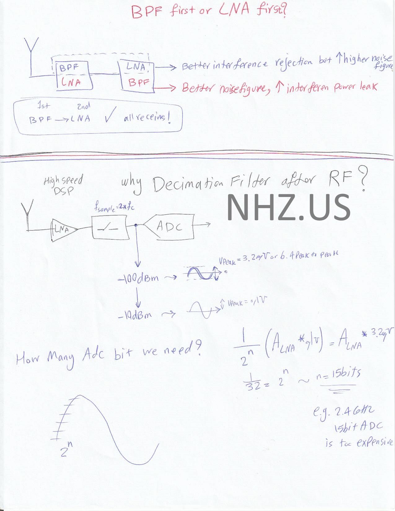
Low Noise Amplifier (LNA) first or Band Pass Filter (BPF):
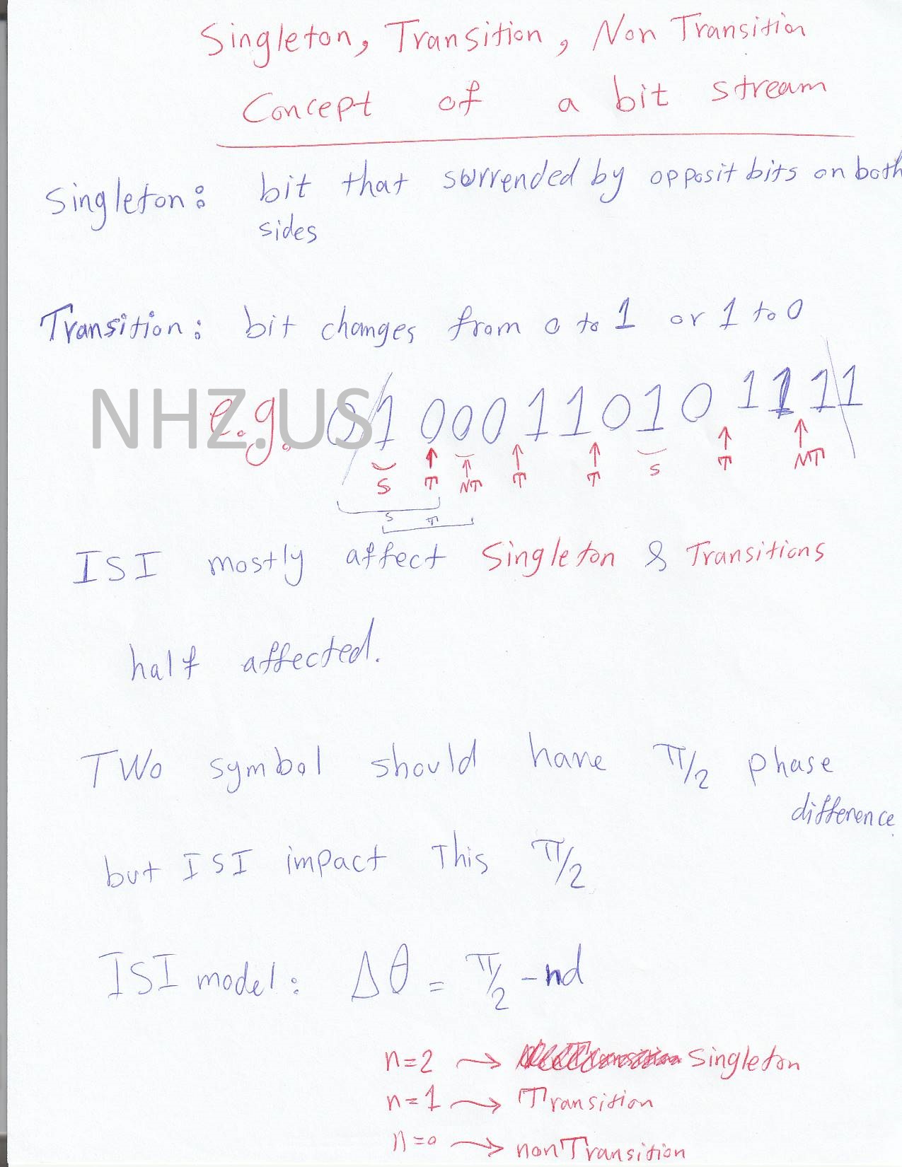
Bit Stream Singleton, Transition and non Transition:
RF Analog Nonlinearity Effects, Third and Second Intercept Point, Harmonic Distortion, Compression Point:


Here is Cascaded Nonlinear Stages:
Dynamic Range in RF Analog:
Two Point Modulation PLL for GMSK & SAR ADC


Here is Cascaded Nonlinear Stages: