Understanding Compression Point as Part of RF Analog Nonlinear EffectCompression points are crucial parameters in RF (Radio Frequency) systems that characterize the nonlinear behavior of RF components. They play a significant role in determining the maximum linear operating range and performance of RF devices. What is RF Analog Nonlinearity?RF analog nonlinearity refers to the phenomenon where the output signal of an RF device is not directly proportional to its input signal. Nonlinear behavior in RF components can lead to distortions, intermodulation products, and degradation in signal quality. Compression PointsCompression points in RF systems indicate the input signal level at which the output signal deviates from its linear behavior. There are two primary compression points: 1. 1 dB Compression Point (P1dB)The 1 dB Compression Point (P1dB) is defined as the input power level at which the output power of the RF device decreases by 1 dB compared to its linear output power. At this point, the RF component begins to compress the signal, meaning further increase in input power results in less proportional increase in output power. 2. 3rd Order Intercept Point (IP3)The 3rd Order Intercept Point (IP3) is another critical parameter related to compression. It represents the output power level at which the third-order intermodulation products generated by nonlinearities equal the power of the original signals. IP3 indicates the linearity of the RF device, where higher IP3 values indicate better linearity and less distortion. Importance of Compression PointsUnderstanding compression points is essential for several reasons:
Measurement and CalculationTo determine compression points like P1dB and IP3, engineers use specialized test equipment such as signal generators and spectrum analyzers: Measurement of P1dBEngineers vary the input power level of the RF device and measure the corresponding output power. P1dB is determined when the output power decreases by 1 dB from its linear value. Measurement of IP3IP3 is measured by injecting two tones into the RF device and measuring the power levels of the fundamental tones and their third-order intermodulation products. IP3 is calculated from the intercept point where the power of intermodulation products equals the power of the original signals. ExamplesExample 1: P1dB Measurement in an RF AmplifierTo measure P1dB in an RF amplifier, engineers increase the input signal power gradually and measure the corresponding output power. P1dB is identified when the output power drops by 1 dB from its linear value, indicating the onset of compression. Example 2: IP3 Calculation in a MixerIn a mixer circuit, engineers inject two tones at specific frequencies and measure the power levels of the fundamental tones and their third-order intermodulation products. IP3 is determined by extrapolating the intercept point where the power of intermodulation products equals the power of the original signals, indicating the mixer's linearity and distortion characteristics. ConclusionCompression points, such as P1dB and IP3, are critical in understanding and managing nonlinear effects in RF systems. By measuring and optimizing these parameters, engineers can design RF devices and systems that maintain high signal fidelity, minimize distortion, and optimize performance across various applications. Question & AnswerQ: What are compression points in RF systems? A: Compression points in RF systems indicate the input signal level at which the output signal begins to deviate from its linear behavior. They include parameters like the 1 dB Compression Point (P1dB) and the 3rd Order Intercept Point (IP3). Q: Why are P1dB and IP3 important? A: P1dB and IP3 are crucial because they define the maximum linear operating range of RF devices and systems. They help in optimizing performance, reducing distortion, and ensuring signal integrity in various RF applications. Q: How are P1dB and IP3 measured? A: P1dB is measured by gradually increasing the input signal power and observing when the output power decreases by 1 dB. IP3 is measured by injecting two tones into the RF device, measuring their power levels, and determining the intercept point where third-order intermodulation products equal the power of the original signals. 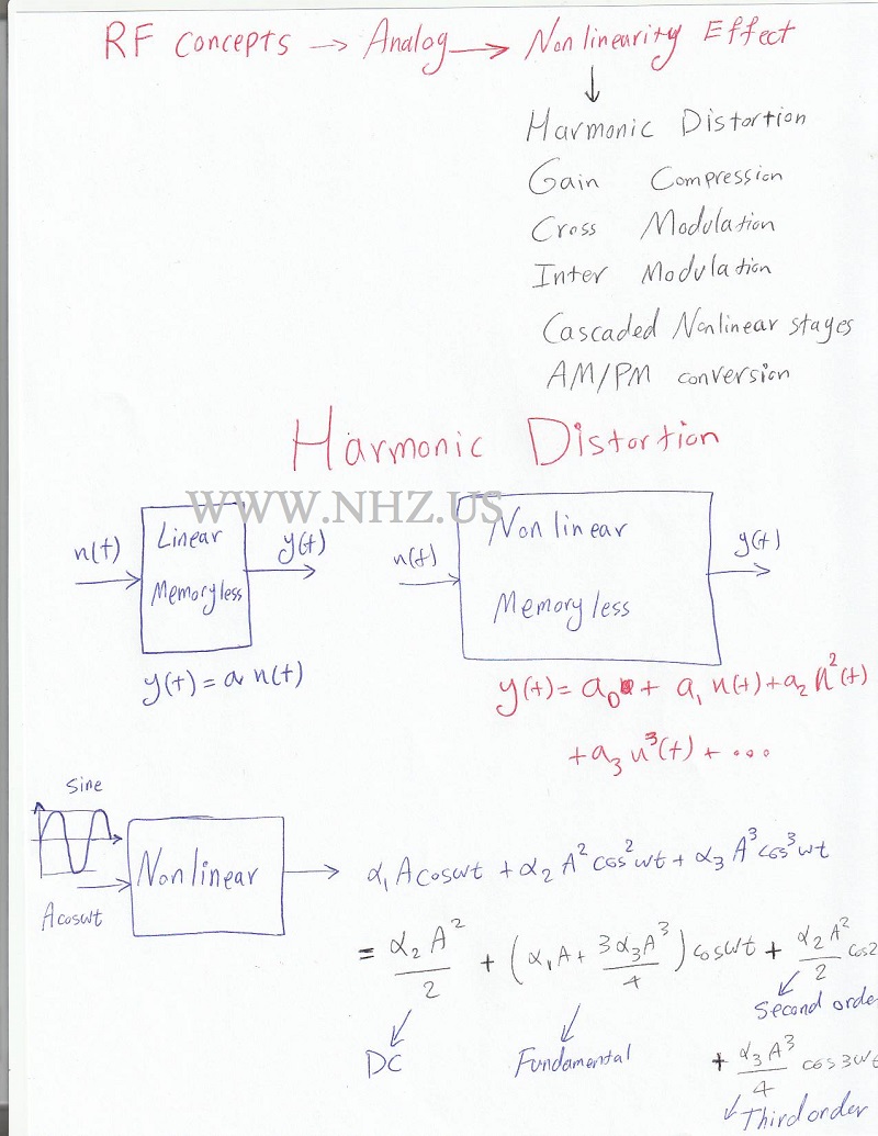 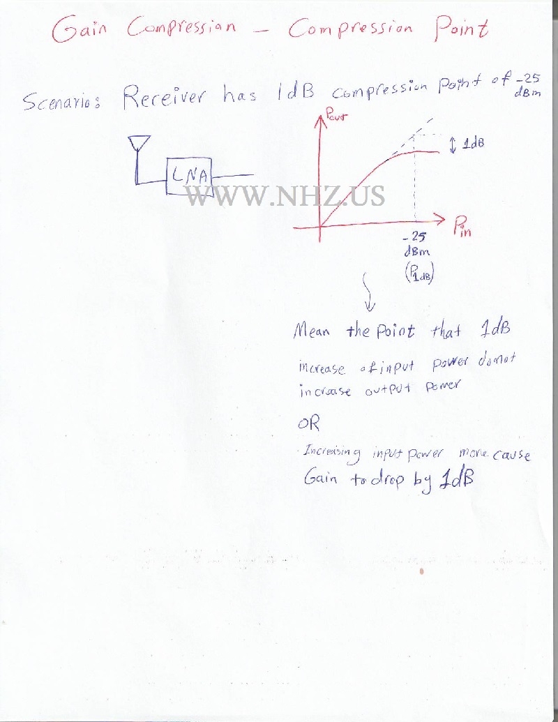  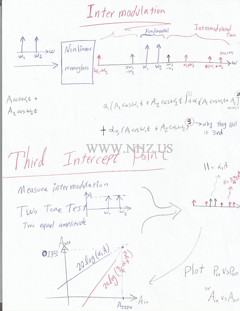   |