Understanding Third and Second Intercept Points for RF Nonlinearity EffectsNonlinearity in RF (Radio Frequency) systems can lead to distortions that affect signal quality. Two crucial metrics used to quantify and mitigate these effects are the Third Intercept Point (IP3) and the Second Intercept Point (IP2). What is RF Nonlinearity?RF nonlinearity refers to the phenomenon where the output of an RF device does not maintain a linear relationship with its input signal. This can cause distortions and the generation of unwanted signals. The Third Intercept Point (IP3)The Third Intercept Point (IP3) is a measure of a system's ability to handle strong input signals without significant distortion. It specifically indicates the point at which the third-order intermodulation products equal the power of the original signals. Understanding Third-Order IntermodulationWhen two signals, A and B, with frequencies f1 and f2 respectively, pass through a nonlinear device, they can produce new signals at frequencies such as 2f1 - f2 and 2f2 - f1. These are third-order intermodulation products, which can interfere with the desired signals. Calculation of IP3To calculate IP3, engineers typically inject two tones into the RF device and measure the output power of both the fundamental tones and their third-order intermodulation products. The IP3 value is then determined by extrapolating the intercept point where the power of these products equals that of the fundamental signals. The Second Intercept Point (IP2)The Second Intercept Point (IP2) measures the linearity of a system against second-order intermodulation products. These products arise from the interaction of two input signals, generating new signals at frequencies like f1 + f2 and f1 - f2. Understanding Second-Order IntermodulationSecond-order intermodulation occurs when nonlinearities cause two signals to mix, producing new signals at frequencies that are sums and differences of the original signals' frequencies. Calculation of IP2IP2 is calculated similarly to IP3 but focuses on second-order intermodulation products. It indicates the intercept point where the power of these products equals the power of the original signals, providing a measure of the system's linearity against second-order distortions. Importance in RF SystemsHigh IP3 and IP2 values are essential for maintaining signal integrity in RF systems:
Mitigation StrategiesTo mitigate nonlinearity effects and improve IP3 and IP2 values, engineers employ several strategies:
Question & AnswerQ: What is the Third Intercept Point (IP3)? A: IP3 is a measure of a system's linearity against third-order intermodulation products. It indicates the point at which the power of these products equals the power of the original signals. Q: What is the Second Intercept Point (IP2)? A: IP2 measures a system's linearity against second-order intermodulation products, indicating the point where their power equals that of the original signals. Q: Why are IP3 and IP2 important in RF systems? A: IP3 and IP2 values determine how well an RF system can handle strong signals without generating distortions that could interfere with the desired signals, crucial for maintaining signal quality and system performance. Q: How are IP3 and IP2 calculated? A: Engineers calculate IP3 and IP2 by injecting multiple tones into the system and measuring the power levels of both original and intermodulation products, extrapolating intercept points where their powers equal. Q: What strategies are used to mitigate nonlinearity in RF systems? A: Strategies include selecting linear components, optimizing biasing, using feedback, implementing filters, and designing with sufficient headroom to minimize nonlinear effects. ExamplesExample 1: IP3 Measurement in an RF AmplifierTo measure IP3 in an RF amplifier, engineers inject two tones at specific frequencies, measure the power levels of the fundamental tones, and then extrapolate the point where third-order intermodulation products reach the same power level as the fundamentals. This determines the amplifier's IP3 value. Example 2: IP2 Enhancement in a MixerIn a mixer circuit, engineers enhance IP2 by selecting a mixer with high linearity, ensuring proper biasing, and implementing filters to minimize second-order intermodulation products. This improves the mixer's performance in RF applications. ConclusionThe Third and Second Intercept Points (IP3 and IP2) are critical metrics for understanding and managing nonlinearity in RF systems. By measuring and optimizing these points, engineers ensure that RF components and systems can maintain high signal integrity and minimize unwanted distortions, thereby enhancing overall system performance and reliability. 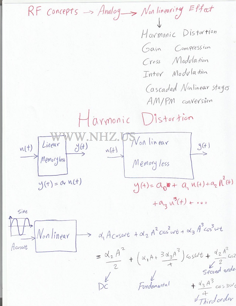   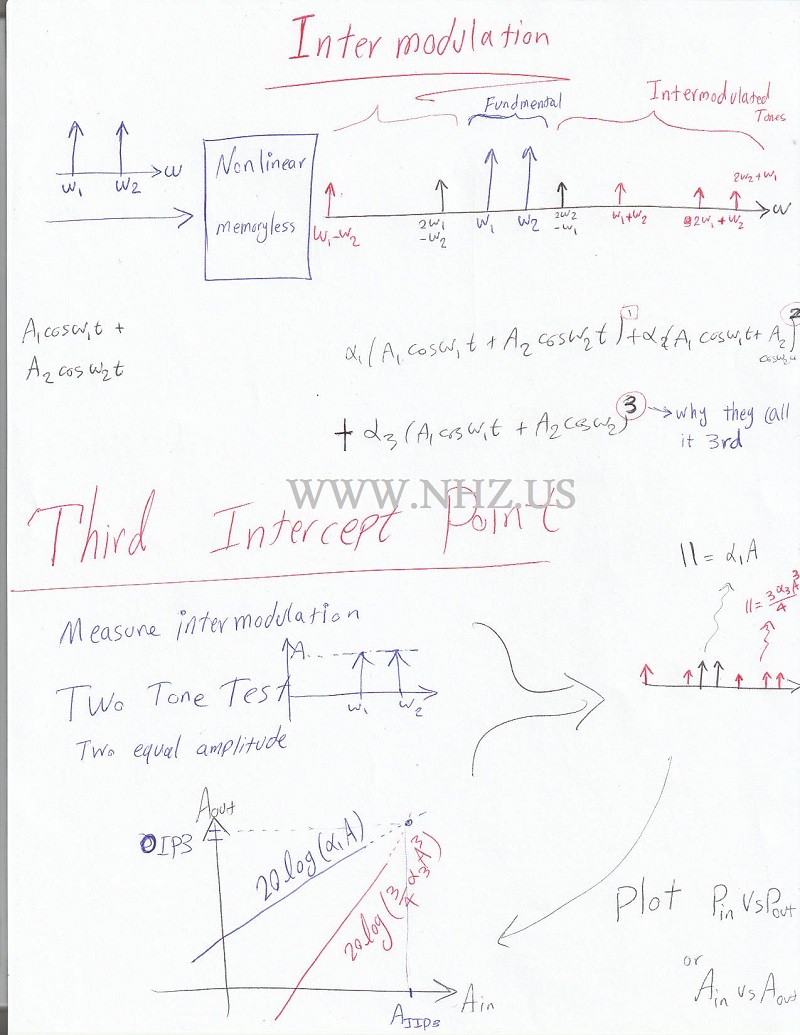 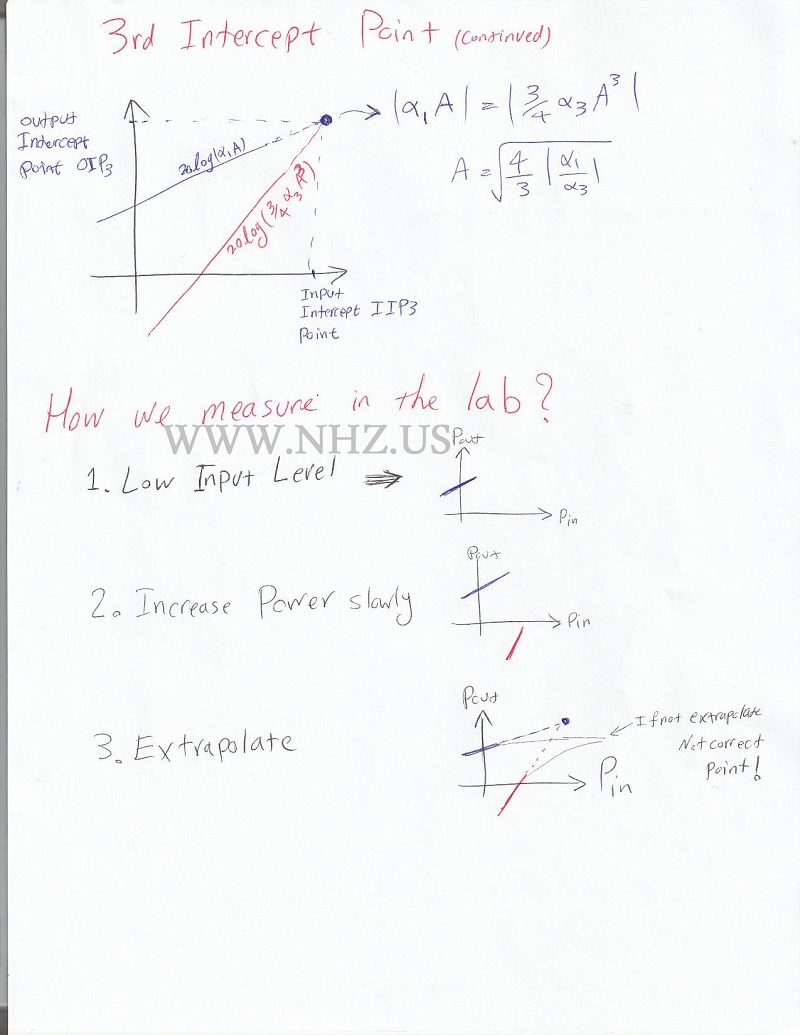 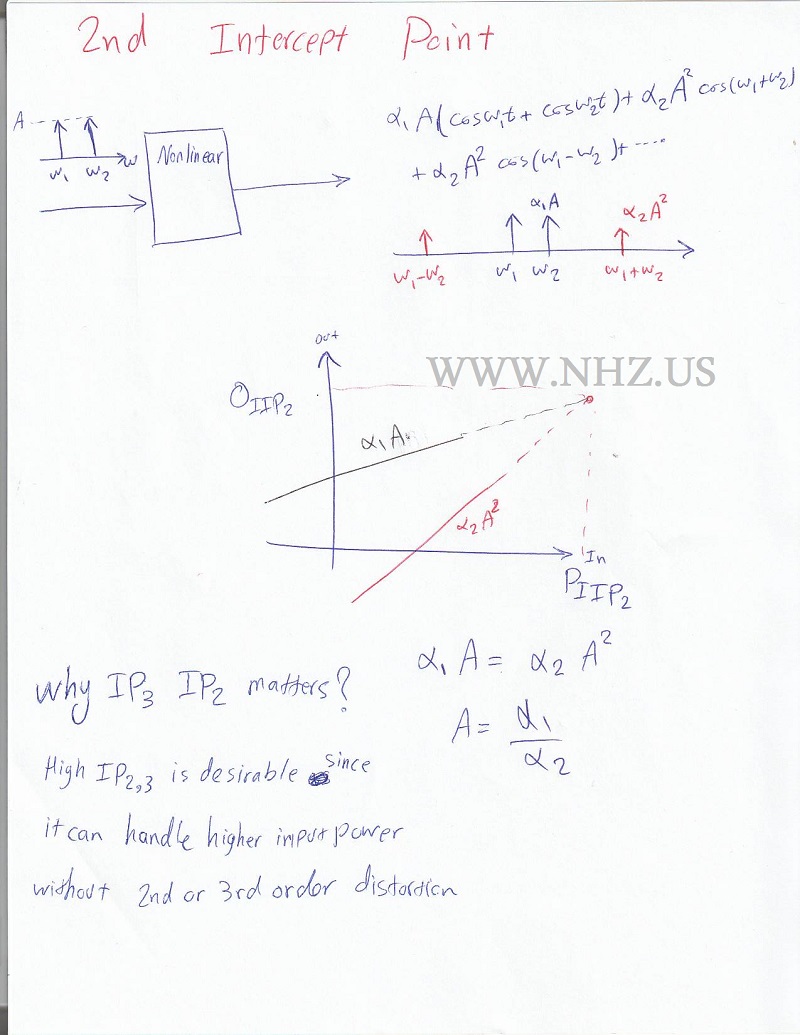 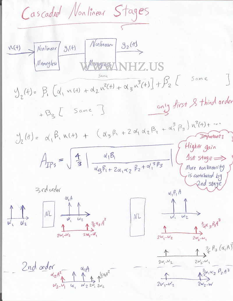 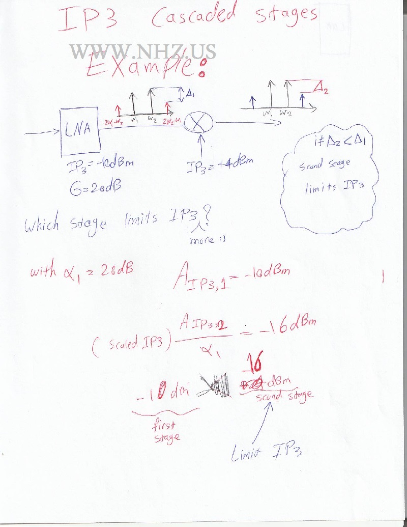 Here is Cascaded Nonlinear Stages: |